
The Rack Battery Design and Build
Ebike battery packs are made from lithium ion cells which provide 3.7v (3.6v for ours) nominal voltage and charge upto 4.2v and can go down to around 3.1v safely with longevity.
When cells are connected end to end (serial) the voltages are combined, so 13 cells end to end, 3.7v x 13 = 48.1v, when charged fully they can provide 54.6v (13 X 4.2V) .
When cells are grouped with all the positive connected as one and all the negatives connected as one (in our case 5 cells) the capacity and the current draw are combined (our Samsung 50E 21700 cells provide a minimum of 4900mah at 9.8A (14.7A max)). Standard Discarge Capacity Min 4900mAh @ 2.5v cut off. Our batterys are genuine samsung from a UK supplier so we can safely say that the ratings are true.
Each cell group of 5 cells can provide 24.5Ah at 49A(5x 9.8A) 73.5A max(5 x 14.7A), so when combined in serles can provide 24.5Ah at 54.6v (4.2v x 13) with a constant current draw capabilty of 49A.
Since the motor is 1500w we would need 31.185A current draw @ 48.1v (1500w / 48.1v), since the battery can provide 49A continuous, this current draw is less and would put less strain on the battery.
In practice the motor has been seen to use 1800w peak, which is 37.42A. Looking around we have seen 1500w rated battery which has a 30A BMS max. Our Smart BMS is rated at 60A constant, with 100A max (Short bursts) to allow for this, and decrease the stress on the components.
The cell life is calculated when the rated capacity is greater or equal to 3802mAh after 500 cycles (80% of rated discharge capacity). This calculation is based on charging to 4.2V (54.6V) and a cut off voltage of 2.5V (32.5V). Cell capacity is measured by charging at 0.5C(2,450mA) per cell to 4.2V, and discharging at 1C(4,900mA), with a 2.5V cutoff. Since every journey will have different discharge rates, capacity can vary.
Jouneys with lots of peak current draw duration, the rider will see a reduction in battery capacity for its journey. Journeys with very little peak power usage will have a greater distance the bike can go. The more you push the peak power during the battery's life, reduces it lifetime, thats why when designing the battery we allowed for this using 10A cells in a 5P configuration.
We decided to have the upper voltage set at 4.1V (53V) when charging and the cuttoff to 3.1V (40.3V). We decided this to increase the lifetime of the battery, this otherside of this is reduce the capacity available. These volatges can be changed if required to increase lifetime or voltage. Modification of these limits is only possible because we use a smart BMS.
The chart below shows the capacity of the cells at various current draw.
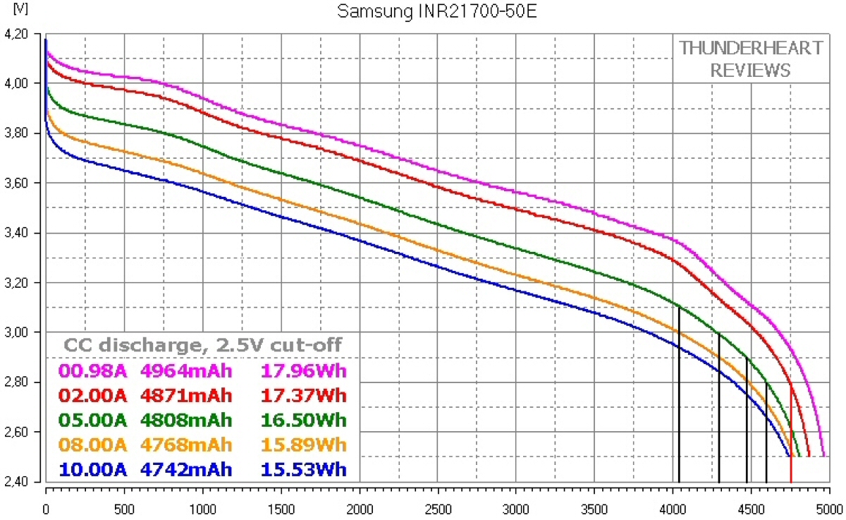
The black vertical lines show the capacity of each cell with a current draw of 5A at various voltage cuttoff limits. the first black line shows the capacity of each cell when a 3.1V cutoff is used. The peak cell voltage set at 4.1V you only loose 25mAh, the lower the upperlimit the greater the longevity of the battery. Using 4.1V to 3.1V would give a cell capacity of around 4025 mAh.
The chart below shows various BMS settings when using a 5A discharge rate
Below is a table used in setting the BMS up to level 3 BMS - 20.25Ah - 53.3V
| Pack Capacity | Cell Capacity | Nominal Voltage | Watt Hours |
High Pack Voltage | Low Pack Voltage | High Cell Voltage | Low Cell Voltage | Usable Capacity | |
| 1 |
18.62Ah | 3725mAh | 48.1V | 895Wh | 52.00V | 41.60V | 4.00V | 3.20V | 76.02% |
| 2 |
20.06Ah | 4012mAh | 48.1V | 964Wh | 52.00V | 40.30V | 4.00V | 3.10V | 81.18% |
| 3 |
20.25Ah | 4025mAh | 48.1V | 974Wh | 53.30V | 40.30V | 4.10V | 3.10V | 82.14% |
| 4 |
21.37Ah | 4275mAh | 48.1V | 1027Wh | 53.30V | 39.00V | 4.10V | 3.00V | 87.24% |
| 5 |
22.37Ah | 4475mAh | 48.1V | 1075Wh | 53.30V | 37.70V | 4.10V | 2.90V | 91.32% |
| 6 |
24.50Ah | 4900mAh | 48.1V | 1178Wh | 54.60V | 32.50V | 4.20V | 2.50V | 100.00% |
Below is a table used in setting the BMS up to a 48.1v Nominal - 20.25Ah (Usable) battery with a range of 4.1V to 3.1v - 53.3V - 40.3V (Number 3 in the list)
| Capacity (V) | Cell Voltage (mV) | Battery Voltage (V) |
||
| 100% | 4100 | 53.3 |
||
| 80% | 3900 | 50.7 |
||
| 60% | 3700 | 48.1 |
||
| 40% | 3500 | 45.5 |
||
| 20% | 3300 | 42.9 |
||
| 0% | 3100 | 40.3 |
The % capacity in mV for each cell voltage is calculated by
(Cell maximum voltage - Cell Minimum voltage) /5
4100mV - 3100mV = 1000mV
1000mV/5 = 200mV
From the cell minimum voltage, the 20% Capacity setting would be
3100mV + 200mV = 3300mV
From the cell minimum voltage, the 40% Capacity setting would be
3100mV + 400mV = 3500mV
This would continue to the cell maximum voltage setting to 4100mV, we do not need this value for these settings, but is a useful guide to check the math is correct.
We are charging these batteries with a 54.6V 3A charger, roughly we are charging each cell at 0.6A (3A / 5) which is well below the standard 2.45A used in capacity testing. When charging at 0.6A we would see an increase in capacity of charge, although not tested. We could charge at 5A for a faster charge if needed, with a different charger and a small tweek to the BMS, although this would reduce the lifetime of the battery and charging capacity.
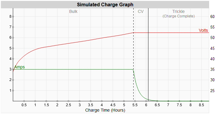
The above diagram shows the charge time for our battery charging at 3A. Time to full charge approx. 6 hours, allow an extra hour on full charge for the cells to balance, the app will show you when all cells are balanced.
We decided on a plan and devised a series of steps to follow
Step 1 - Divide the space in to cells, to see how many cells fit in the space
We used an online calculator (Russian battery space calculator) to estimate how many cells we could fit into the space we had. The above link shows us that we had enough space for 65 cells 13s5p and the BMS.
We used a cell dimension of 23mm (allows for spacers) with a 2mm gap all around our cells.
Step 2 - Place the cell in the order that best fits the space
Step 3 - Place the other parts like BMS etc in the space
Step 4 - Groups the cells
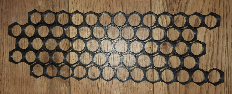
Above are the cell spacers connected to match cell layout using 13 long spacers x 5 rows
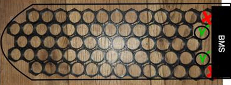
The above picture shows which cells of the spacers are needed
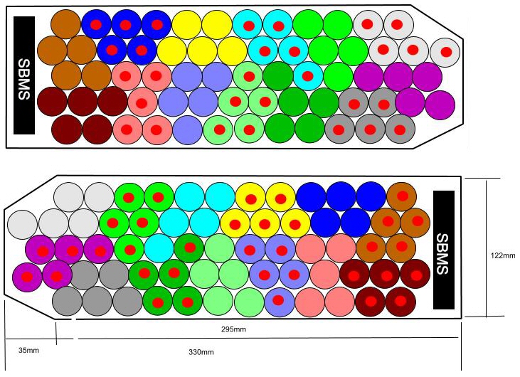
The rows are as follows :-
Row 1 - 12 cells, Row 2 - 14 cells, Row 3 - 13 cells, Row 4 -14 cells and Row 5 - 12 cells
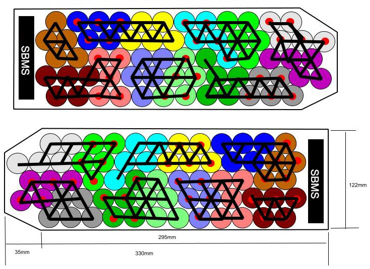
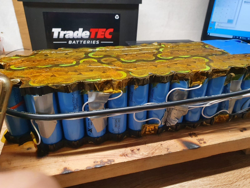
Once the spacers are fitted top and bottom the nickel strip diagram is designed. There are 13 groups with 5 cells in each group. Each strip is made from pure nickel strip 10mm wide and 0.2mm thick. Each group is connected positive to negative in a pattern that winds its way around the battery pack, so that the negative and positive end near the BMS. Each cell has at least 2 connection to its neighbouring cell or group.
The negative terminal is top left (brown group of 5) of top pictue and the positve terminal is bottom right (burgundy group of 5) of the bottom picture.
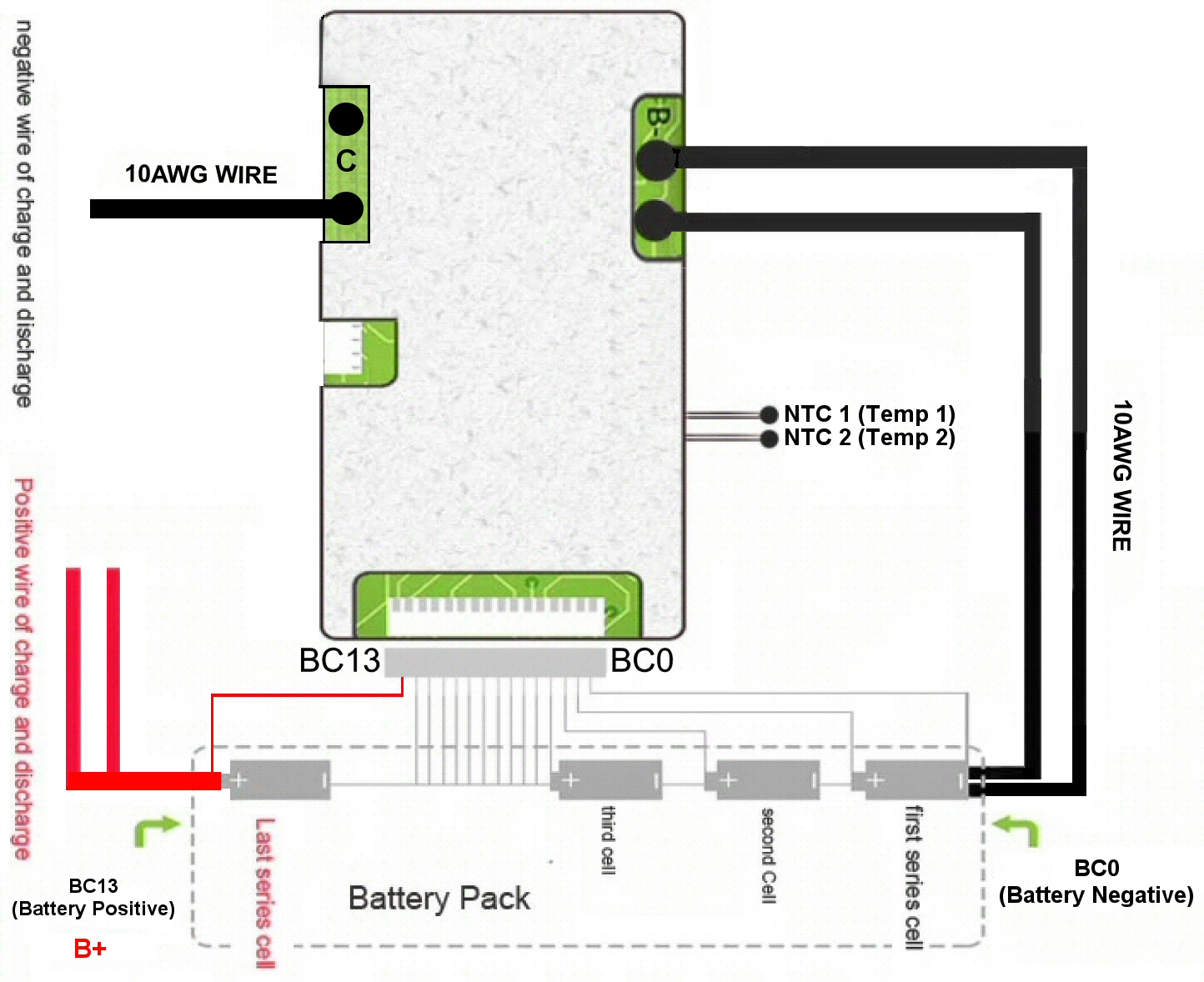
Below is a diagram of the bms balance wire connections. We start with B0 on the first negative, then B1 being the first positive working our way to B13 (red wire) , being the last positive.
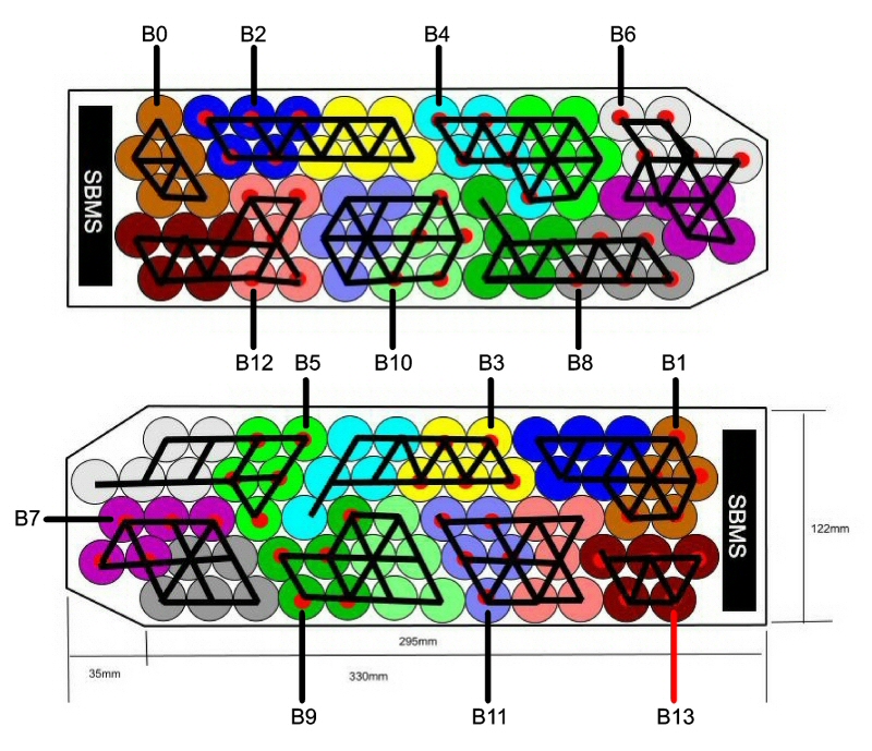
BMS Wiring Diagram
 |
 |
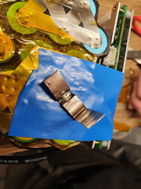
|
| Nickel strip bus bars for connections | Getting ready to weld bus bar into place |
 |
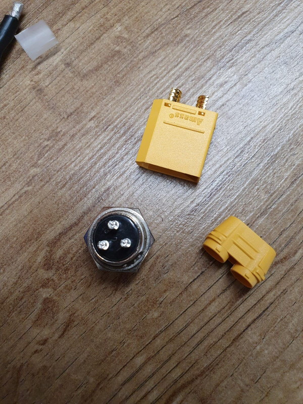 |
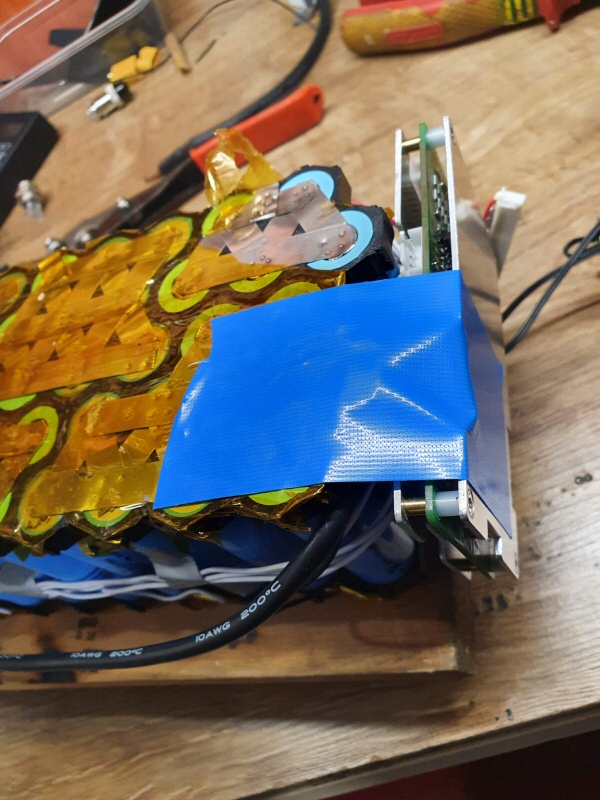
|
| Power cables installed | XT90S and charger connections |
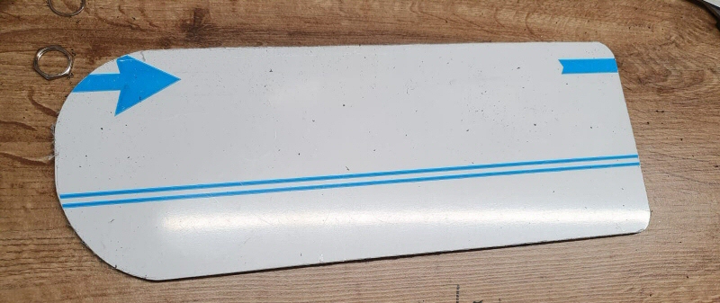
Composite board cut to shape
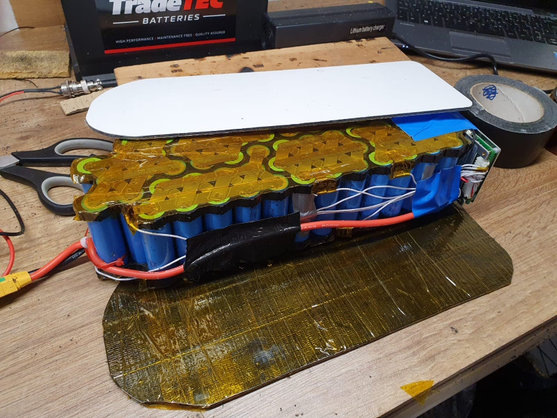
Composite board for battery top and bottom with electrical insulation
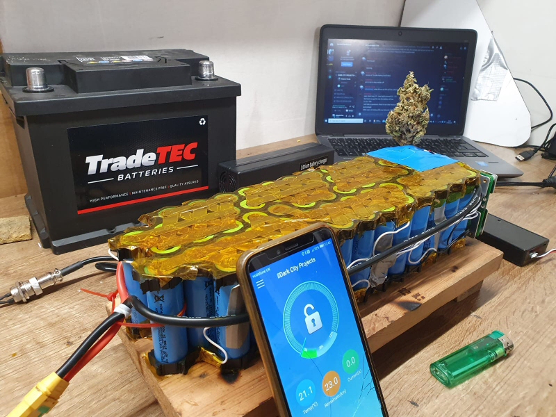
Everything assembled and charging at 54.6V at 3A. The battery can be switched off or off via the app on the phone, connected by the bluetooth module connected to the BMS.
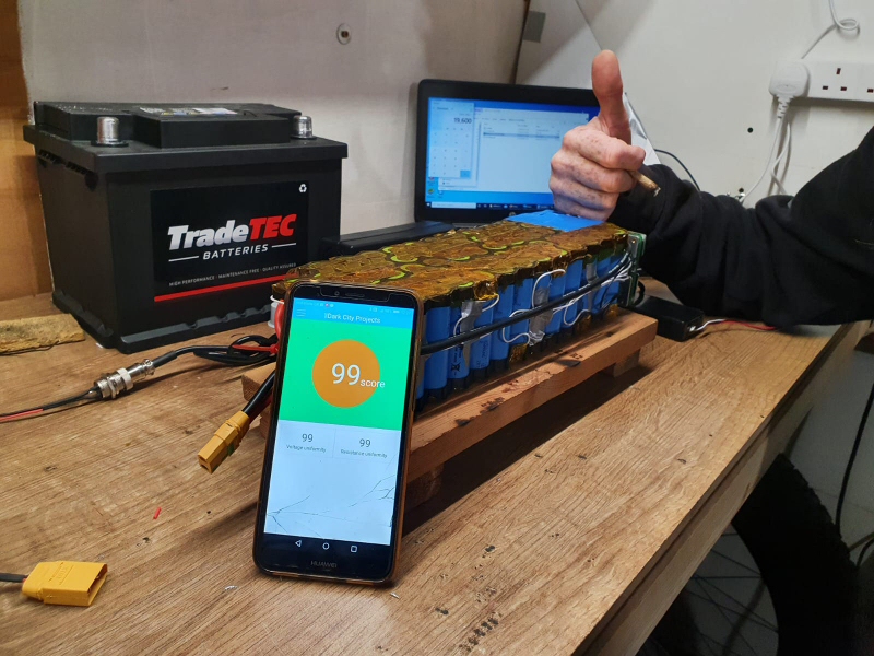
The app is dispalying the battery quality. 99% on all score !!!
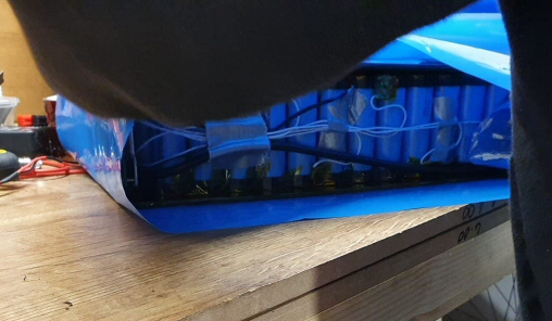
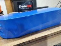
Shrink wrapping the battery
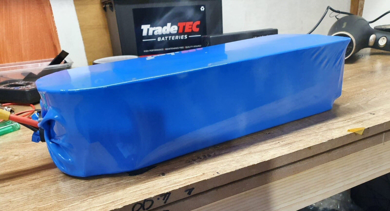
After shrink wrapping
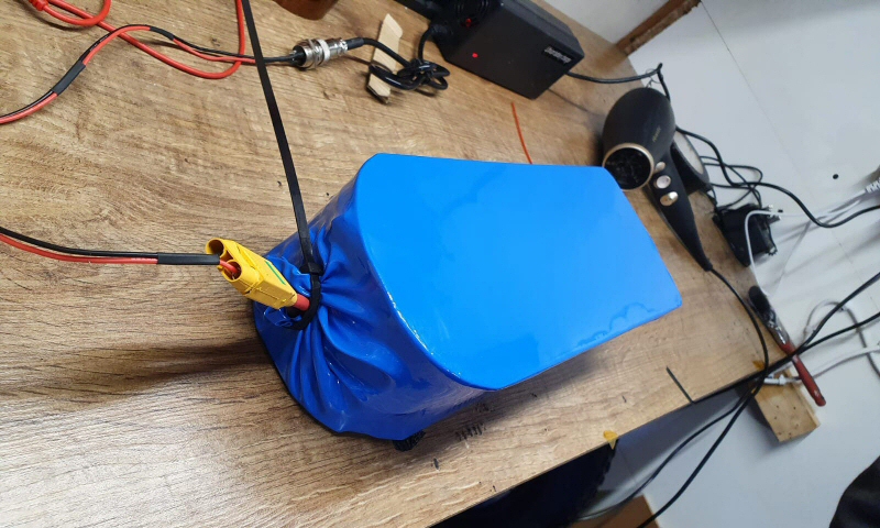
Charging after shrink wrapping
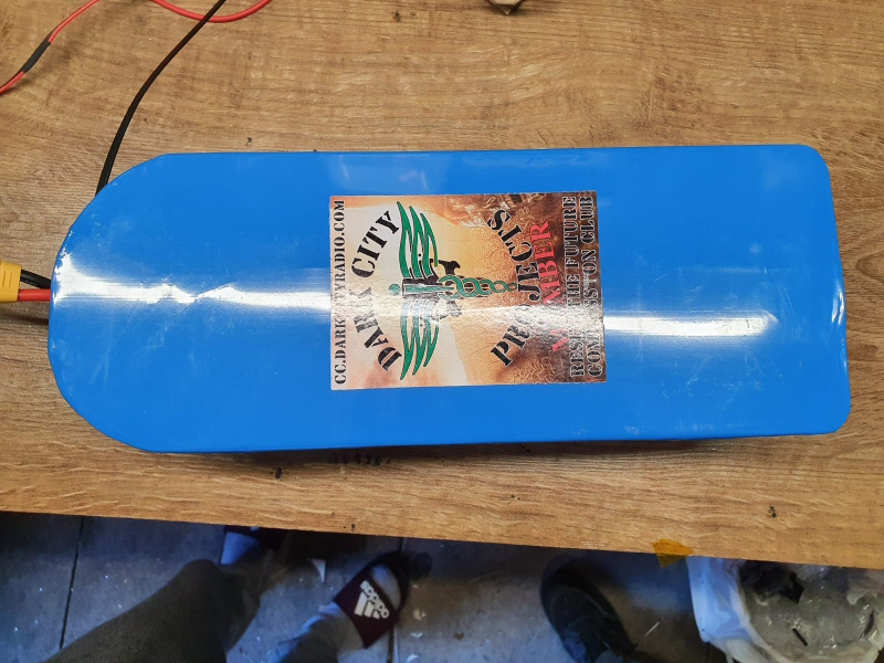
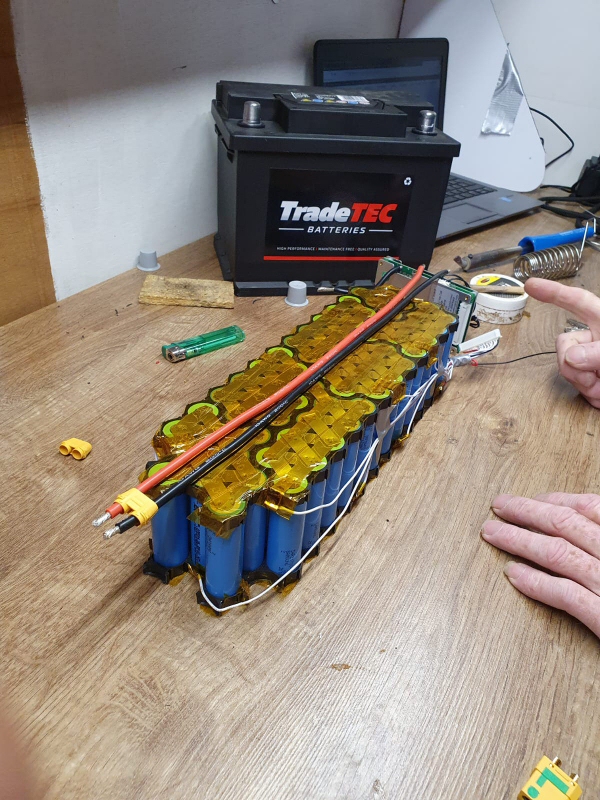
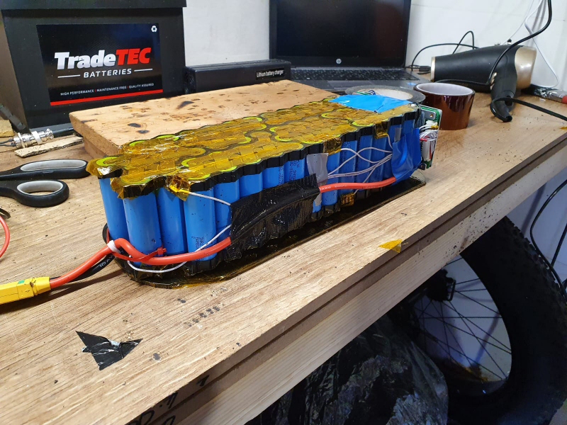
Another Battery built with Dark city projects this time from 65pcs Samsung 21700 50E cells, pure Nickel strip 0.20 x 3, with 60A Smart BMS. The Discharge capacity is 49A upto 73.5A. Total Capacity 24.5Ah @ 48.1V (4.2v to 2.5v) and fits on rear carry rack.
We are running our cells from 4.1v to 3.1v, which we set in the BMS, this way the life of the battery pack should last much longer, but does reduce the overall capacity and peak voltage. Ttotal capacity available at these voltages gives us a capacity of 22.6Ah which is 92.35%, this extends the life of the battery from >500 cycles to >1000 cycles (low estimate). 500 cycles is around 1.36 years charged once a day, 1000 cycles is around 2.73 years.
BMS app with a rating for the battery
The app can be downloded from click here
Some versions of the app work better on different phones and android versions.
There is a cutdown version on google play store but does not have all the extended features.
Below are links for software for the pc data port and settings instructions
PC Communication software - JBDTools V1.6-20170622
JBDTools (BMS) Detailed parameter settings
Samsung 50E datasheet
Coming soon - The Rack Battery V2
