
Bobs Bigger Battery Bike
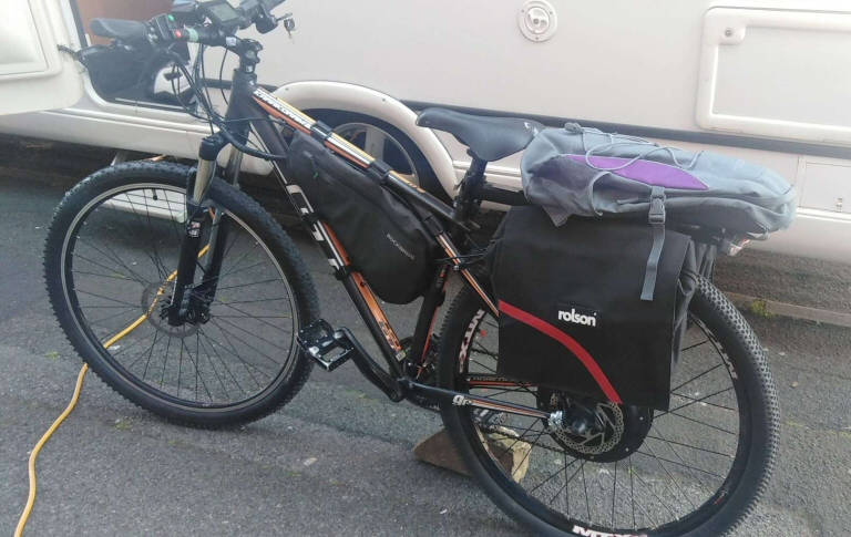
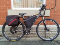
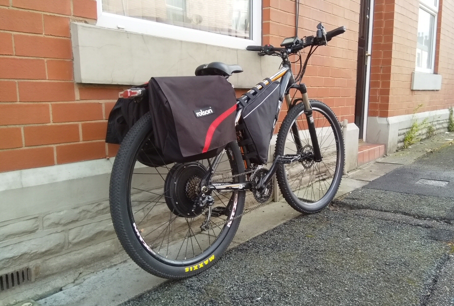
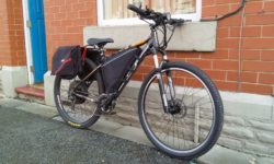
Bobs bike before with a 20Ah lipstick battery in the grey and purple bag.
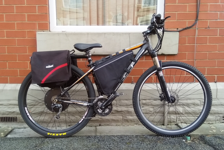
The speed controller and wiring is in the triangular frame.
We wanted to design a better battery for Bob's Ebike to replace his 20Ah 48v lipstick battery, we decided originally on a 30Ah 48.1v battery but decided to add extra cells to make it 34.3Ah 48.1v. To make our 34.3Ah battery we designed it in a 13S7P configuration.
Ebike battery packs are made from litium ion cells which provide 3.7v (3.6v for ours) nominal voltage and charge upto 4.2v and can go down to around 3.0v safely with longevity.
When cells are connected end to end (serial) the voltages are combined, so 13 cells end to end, 3.7v x 13 = 48.1v, when charged fully they can provide 54.6v (13 X 4.2V) .
When cells are grouped with all the positive connected as one and all the negatives connected as one (in our case 7 cells) the capacity and the current draw are combined (our Samsung 50E 21700 cells provide a minimum of 4900mah at 9.8A (14.7A max)). Standard Discarge Capacity Min 4900mAh @ 2.5v cut off @ 0.98A. Our batterys are genuine samsung from a UK supplier so we can safely say that the ratings are true.
Each cell group of 7 cells can provide 34.3Ah at 68.6A(7 x 9.8A) 102.9A max(7 x 14.7A), so when combined in serles can provide 34.3Ah at 54.6v (4.2v x 13) with a constant current draw capabilty of 68.6A.
Since the motor is 1500w we would need 31.185A current draw @ 48.1v (1500w / 48.1v), since the battery can provide 68.6A continuous this current draw is considerably less and would put less strain on the battery.
In practice the motor has been seen to use 1850w peak, which is 38.5A. Looking around we have seen 1500w rated batterys is a 30A BMS max. Our Smart BMS is rated at 60A to allow for this, and decrease the stress on the components.
The cell life is calculated when the rated capacity is greater or equal to 3802mAh after 500 cycles (80% of rated discharge capacity). This calculation is based on charging to 4.2v (54.6v) and a cut off voltage of 2.5v (32.5v). Cell capacity is measured by charging at 0.5C(2,450mA) per cell to 4.2V, and discharging at 1C(4,900mA) per cell, with a 2.5V cutoff. Since every journey will have different discharge rates, capacity can vary.
Jouneys with lots of peak current draw duration, the rider will see a reduction in battery capacity for its journey. Journeys with very little peak power usage will have a greater distance the bike can go. The more you push the peak power during the battery's life, reduces it lifetime, thats why when designing the battery we allowed for this using 10A cells in a 7P configuration, and only using just over half its current capabilty.
We decided to have the upper voltage set at 4.1v (53.3v) when charging and the cutoff to 3.1v (40.3v). We decided this to increase the lifetime of the battery, this otherside of this is reduce the capacity available. These volatges can be changed if required to increase lifetime or voltage. Modification of these limits is only possible because we use a smart BMS.
We are charging these batteries with a 54.6V 3A charger, roughly we are charging each cell at 0.42A (3A / 7) which is well below the standard 2.45A used in capacity testing. When charging at 0.42A we would see an increase in capacity of charge, although not tested. We could charge at 5A for a faster charge if needed, with a different charger and a small tweek to the bms, although this would reduce the lifetime of the battery and charging capacity.
Below is a chart detailing the characteristics of the Samsung 50E
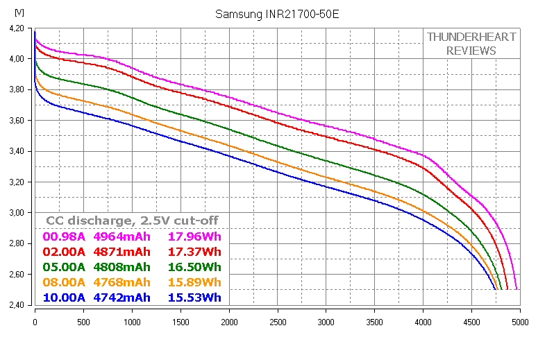
The chart shows the discharge capacity and voltage, battery stats are calculated at 0.98A discharge per cell.
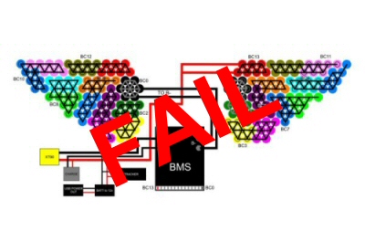
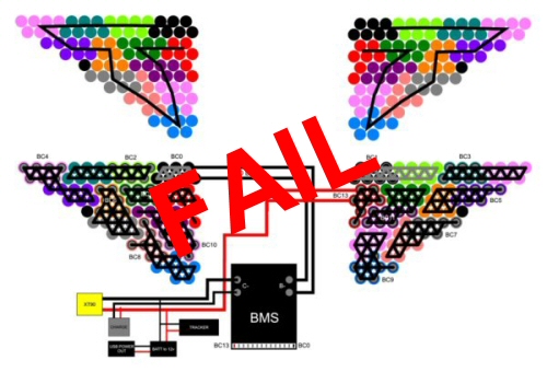
The diagrams below show the cell group layout with interconnecting nickel strips, BMS, connector and auxilary items.
|
|
 |
| Path of the circuit | Battery Circuit |

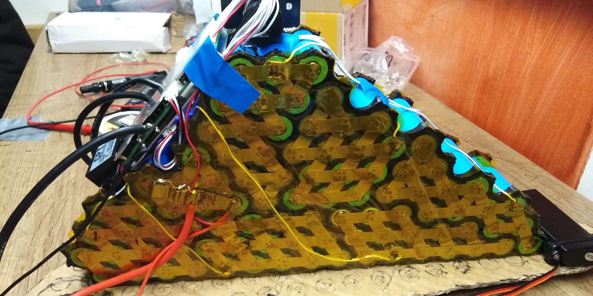
Below is another version battery which was not suitable and circuit layout is not correct
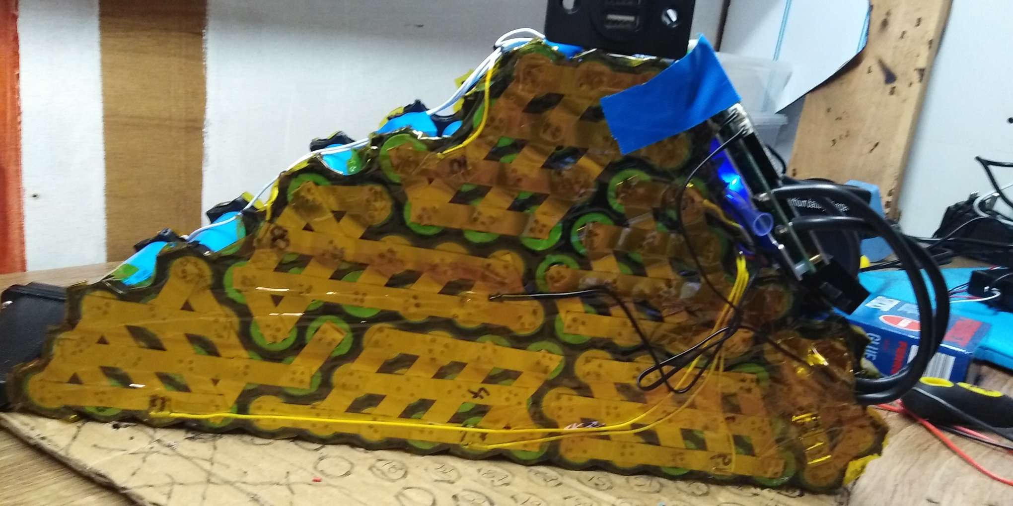
After all the previous atempts now we got it right 3rd time lucky and below is the last an correct battery layout.
Layout - Cell group interconnects and balance connections
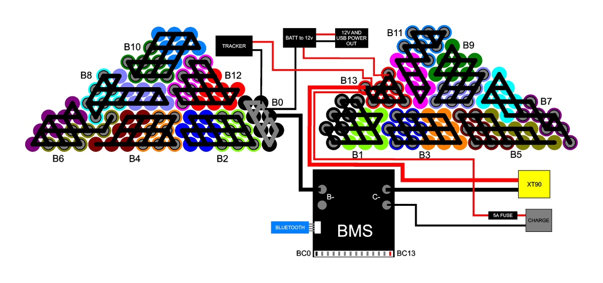
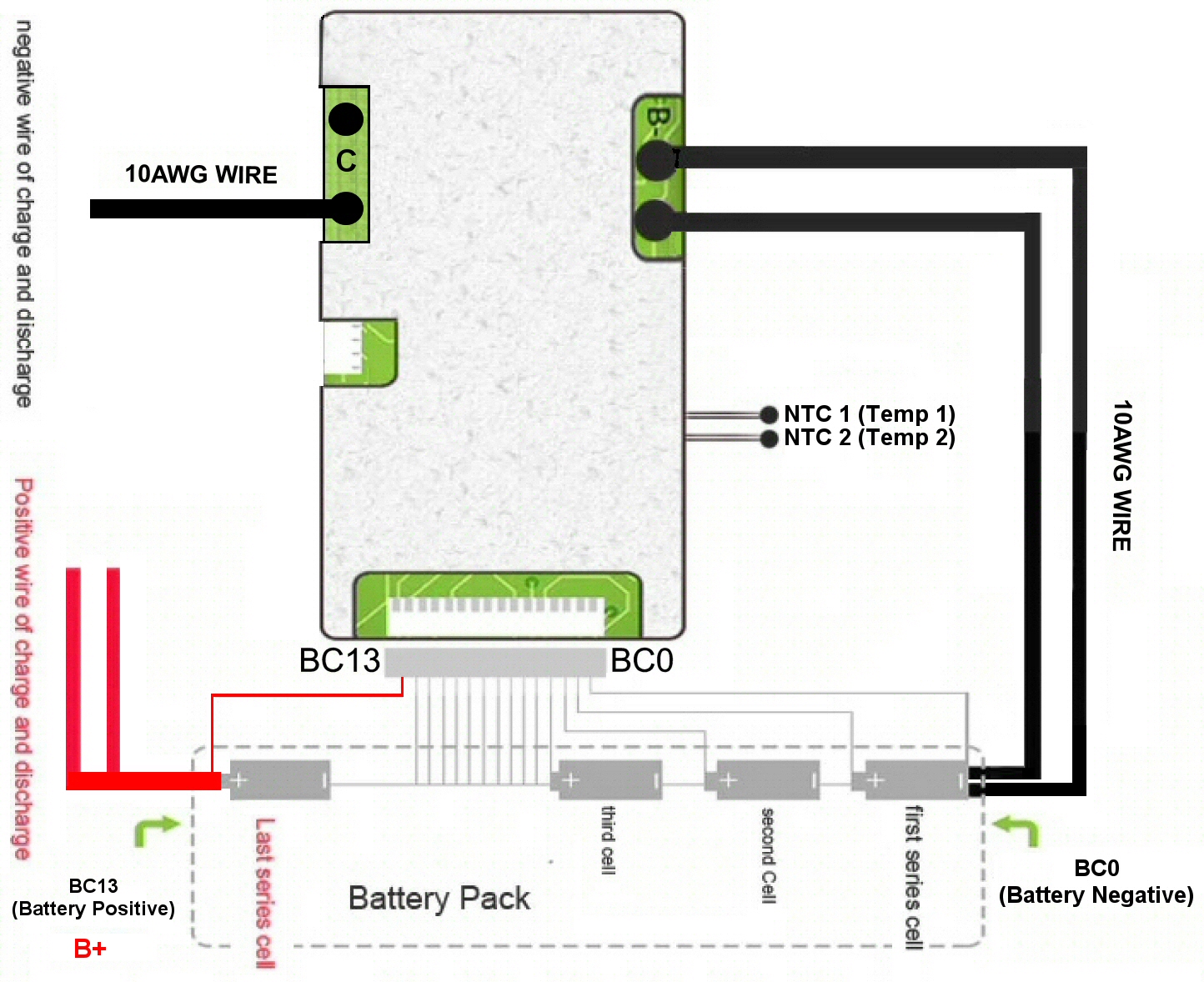
Diagram of BMS connections from manufacturer's website
Below is the instructions for the bms from the manufactuer
Notice of connection :
A. Firstly ,Please connect bold wires from B- port of the BMS to the negative port of the battery pack .(B- wire should be as short as possible) ,then connect these voltage detection wires (Please take off these wires from the BMS before connecting these wires to the battery to avoid any connection mistakes)
B. Second ,Please start connect these balance wires to the Battery system from BC0 ,Black thin wire should be connected to the battery negative , and the second wire -white wire BC1 should be connect to the positive port of the first series cell . BC2 should connect to the positive port of second series cell ,and BC3 wire to the third cell’s positive …connection in this way in order one by one till to the last cell postive port
C. Third . After connection of these balance wires finished , please measure connector voltage from each Neighbouring wires ,the voltage between each neighbouring wires for Li ion battery should be less than 4.2V ,after checking the blance wires are in the correct order, you can plug cable connector into the BMS – wrong connection order will damage our BMS. Please be carefully with this step.
D. Finally , connect C- wire as negative of charge and discharge, B+ wire as positive of charge and discharge , those wires should use thick wire to make connection for large current distribution. Then compare the voltage from the BMS and voltage directly from the Battery, to see if they are the same or not. if they are the same value your connection is correct, otherwise terrible things will happen !!!
In our case our nominal volatage of the cells is 3.6v (they come charged to this voltage), the voltages on each of the balance wires should be as follows :-
| B1 3.6V | B2 7.2V | B3 10.8V | B4 14.4V | B5 18.0V | B6 21.6V | B7 25.2V |
| B8 28.8V | B9 32.4V | B10 36.0V | B11 39.6V | B12 43.2V | B13 46.8V |
Cell spacer technical drawing
![]()
The above drawing is for a 5 cell spacer for sizes but we use 13 cell spacer
Layout - layout and circuit
 |
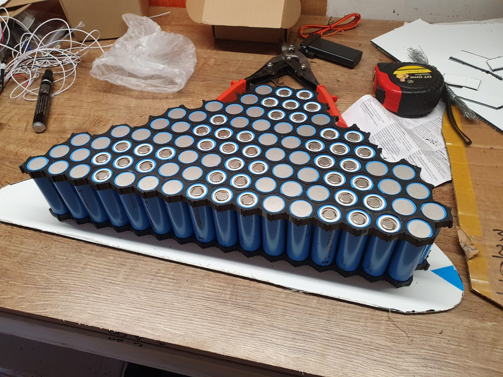 |
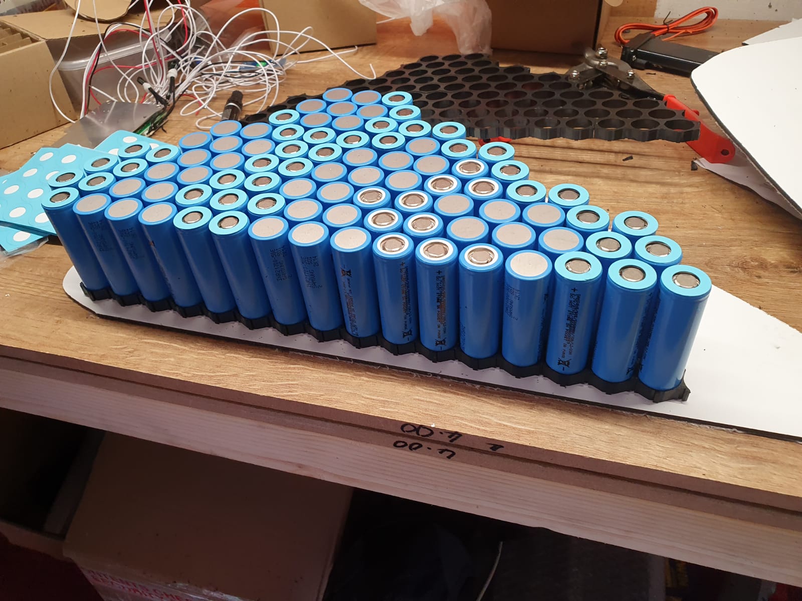
| Cell layout | Cells layed out with spacers both sides |
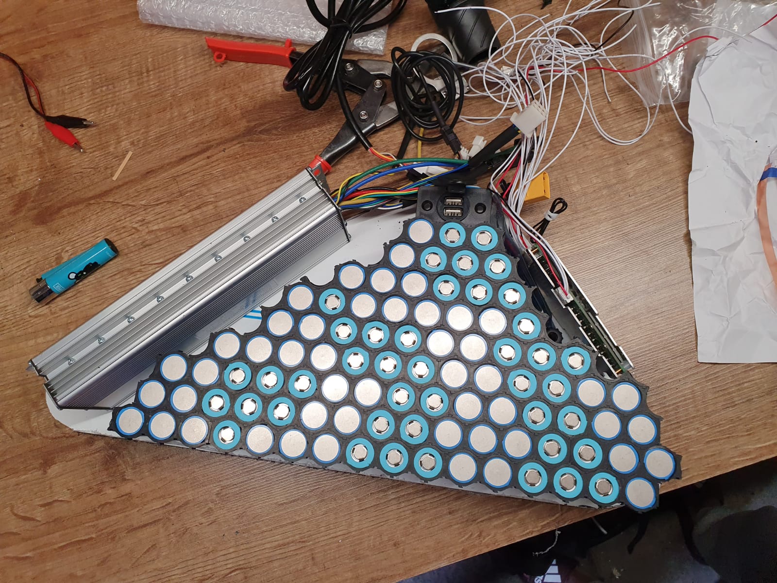
Cells on a template with the speed controller and bms. The blue rings are stickers that give the positive terminals more insulation.
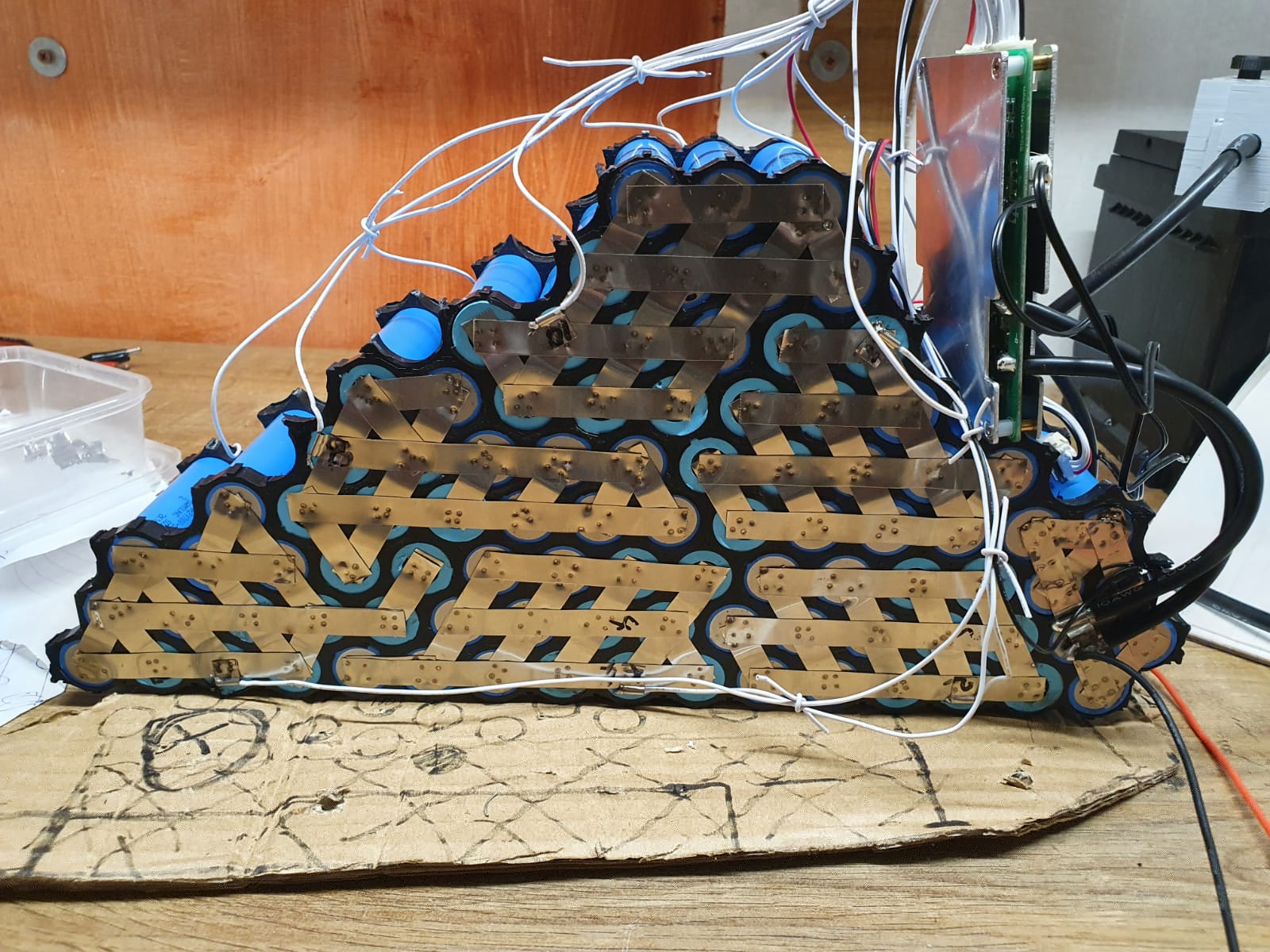
Cells with 10mm 0.2mm pure nickel strips welded and BMS installed
The BMS we chose is a 13S (13x4.2v) 48.1v, 60a continious rating with bluetooth. The bluetooth connects to an app on a phone and allows the user to change parameters on the battery (it can also be connected to a pc with a serial interface using the same port as the bluetooth module)
Negative side of battery with high temperature and electrical insulation tape.
 Positive side of battery with high temperature insulation tape.
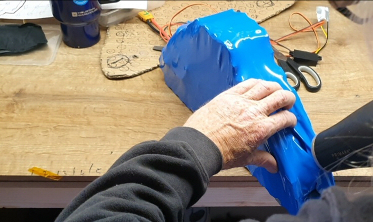
Adding shrink wrap onto the battery
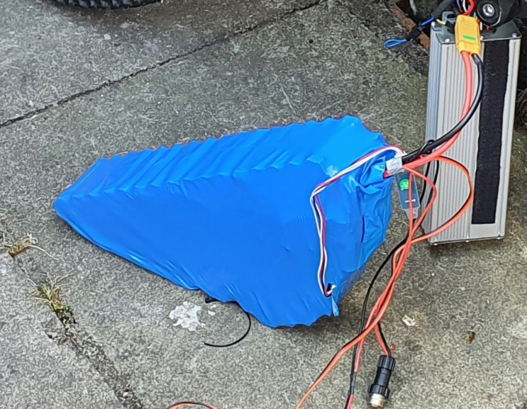
Testing the battery with speed controller and motor.
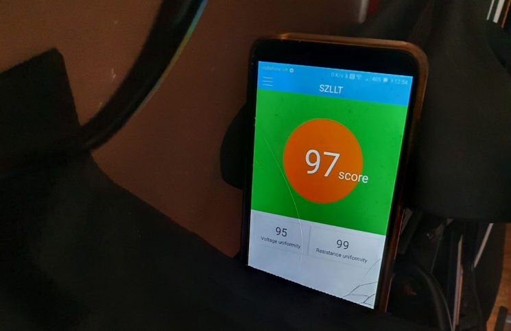
BMS app with a rating for the battery
The app can be downloded from click here
Some versions of the app work better on different phones and android versions.
There is a cutdown version on google play store but does not have all the extended features.
Below are links for software for the pc data port and settings instructions
PC Communication software - JBDTools V1.6-20170622
JBDTools (BMS) Detailed parameter settings
Samsung 50E datasheet
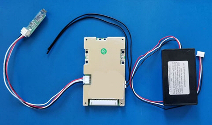
48V 60A smart BMS (Bluetooth left , PC data port right)
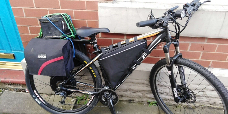
Bob's Ebike with battery installed into bag and transporting a battery for the welder.
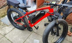
Bobs Bike with new battery which includes bluetooth, gps, dual usb power, 12v light socket, movment sensor and geofencing.
.
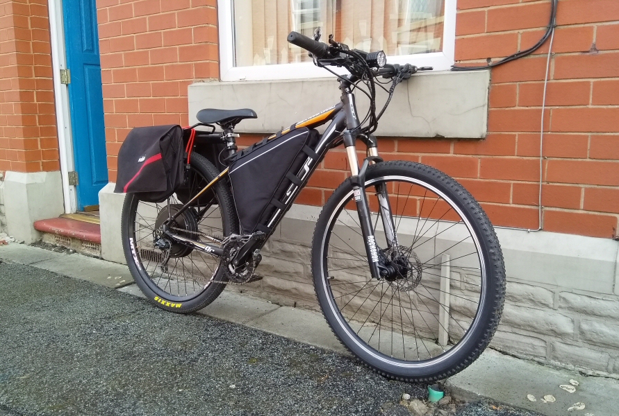
Bobs bike charged and ready for a ride
Bobs bike after a long run, still good to go for another run !
Equiment and parts
Equipment
| Malelctrics Welder | Flux | |
| 12v Car battery 520A CCA | Screwdrivers | |
| Metal Cutters | Hair dryer | |
| 50w Soldering iron | Smart Phone | |
| Wire cutters |
Misc tools |
Parts
91 Samsung 50e 5000mah 10A lithium ion cells Datasheet for cells
LLT SMART BMS with blue tooth 48v 60A contious
1M 12 or 10 AWG Silcone coated cpper wire in red and black
1M 8A Silicone coated copper wire in red and black
5M 10mm 0.2mm Pure nickel strip
13 cell 21700 hex spacers (bought in packs of 50)
100pcs Cell positive insulation pads
1 set of XT90 power connectors (anti spark)
1M 2mm Solder
Waterproof connector for charging port
2M heatshrink for battery pack (Blue)
Heatproof electrical insulation tape
Composite board
Blue duct tape
Cable ties
60v to 12v power converter
Waterproof 12v dual port usb socket ( acts as 12v car lighter socket too)
GPRS Tracker + 2G COMPATABLE SIM CARD
54.6v Ebike charger 3A
3 Pin charging port
7-50V to 12V DC to DC Converter
We received a message on our discord server and thought it worthy to post here.
Incredible work which will make a huge difference to Tazs life. Based on what we're seeing with regards to suppression of freedom in so many aspects this is a much needed form of transport and based on models they themselves are putting into the mainstream e bikes are certainly a massive part of the future.
The cloud of legislation is in the sky but for now a human is apparently allowed to move around on an ebike without restriction, I'm not talking about speed which they already try to limit but just getting out.
It's amazing how the freedom of life Dark City fights for transcends all levels of existence from actually just being alive to being able to move whilst alive. Such a shame the system is not built on love which allows logic to flow into as fair a system as possible. Whether people wish to call it anarchy (not the film version of everything going nuts) or as I always see Dark City something that transcends those labels.
What I'm simply trying to say is well done
After building my own battery's I would never use anything else. It will cost you a little time to build, or get someone you know and trust to build your battery's. What you have to ask yourself, is this just a fad or are you into e-biking for more than 2 years.
So far i have not found any battery on the market that's are setup to last, they running at 100% this is killing off cells in 600 to 1200 recharges, good for selling overpriced batteries, remember its take just one cell to die and your looking for another battery. Using a smart BMS at 80% on 18mm cells will give you 1200 to 2400 recharges, the newer 21mm cells running at 80% have done a lot more that 2400 discharge cycles, the truth is at 60% they could be running longer than most of us.
I can not tell you if my home built battery will last longer, but if i ever i come to sell it the new owner can see what real life is left in it. Best of both worlds is to fit a second rack battery with SBMS built out of 21700 or better cells, run the test your self. It will cost a little more if anything and its has a lot better chance of out lasting anything of the shelf. if its not a fad, its the only way to go.


0 Responses