|
|
Quick Link Downloads |
 |
|
| Samsung 50E Datasheet | JBDTools V1.6-20170622 | ||
| BMS Apps | BMS Settings 51.8v 5.5A | ||
| BMS Wiring |
USB Drivers |
||
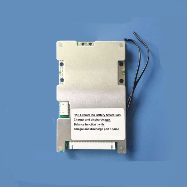
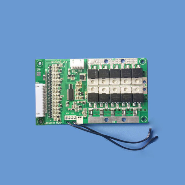
15S 60A BMS WITH BLUETOOTH
 |
 |
|
| 15S Lititium ion Smart BMS Charger (Discharge 60A) | ||
 |
 |
|
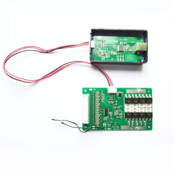
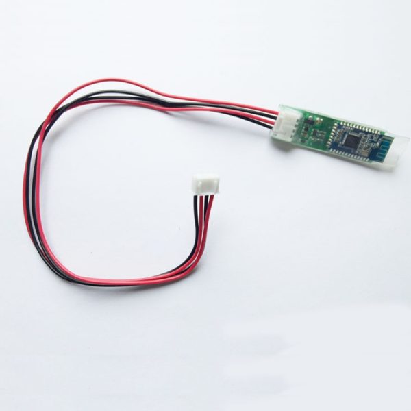
| PC Communication Tool Connected to The BMS | BMS Bluetooth Module (Please note 10v supply) | |
What we are doing here is something different.
We currently have a 13S7P battery which is 41.8V Nominal and 54.6V (53.3V) Full Charge, and we are changing its configuration to a 15S7P battey (55.6V nominal, 63V fully charged), but setting the BMS to be the same voltage as a 14S7P (51.8V nominal, 58.8V fully charged). The voltage of a fully charged 14S battery is 58.8V, so we need to set the maximum voltage of each cell to match.
Rather than charging a 14S to 14 x 4.2V = 58.8V, we are charging a 15S to 15 x 3.92 = 58.8V, giving us greater battery lifetime and maintaining 58.8V fully charged to maximumize speed. So by using a 15S configuration with the maximum voltage of each cell set to 3.92V we would acheive the desired maximum voltage of a 14S battery.
If arrange our cells is a 15S configuration and calculate what maximum voltage of each cell we would need to match the fully charged voltage of a 14S, retaining our desired fully charged voltage and further extending the battries lifetime.
Fully charged 14S = 14 x 4.2V = 58.8V
If we devide the fully charged voltage of a 14S and divide that by 15, that would give us the voltage we need to charge each cell.
58.8V / 15 = 3.92V
Double checking our math
15 * 3.92V = 58.8V
We have decided we want to set our 15S BMS to have a voltage range for each cell to 3.92v (58.8V) to 3.1V (46.5V). By doing this we do reduce the usable capacity of the battery, but increase the longevity of the battery.
Lowering the fully charged cell voltage to 3.92V from 4.2V reduces our cell capacity by around 125mAh, so we only loose a small amount of capacity, but the longevity of the cell is greatly increased.
Setting the lower cut off voltage of each cell from 2.5V to 3.1V also reduces our cell capacity, we loose 750mAh amount of capacity, but the longevity of the cell is greatly increased.The lower end voltage has a more pronounced effect on the longevity of the battery.
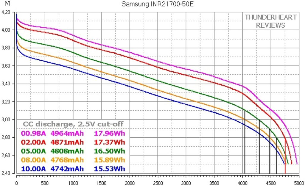
If we look at the graph, when we look at the vertical voltage axis at 3.1V and go along the horizontal capacity axis to the point on the green 5A discharge rate curve reaches 3.1V point on the vertical axis, and follow the black line to the horizontal capacity axis, we get a reading of 4050mAh.
Since we would loose 125mAh due to the upper voltage being 3.92V we would have to remove this from the capacity.
So from our 4900mAh Samsung cells we get
4050mAh - 125mAh = 3925mAh for each cell
Since we have a 7P arrangement we would multiply our 3925mAh x 7 to give us our usable capacity of our battery.
Our fully charged voltage would be 15 x 3.92V = 58.8V
and our capacity would be 3925mAh x 7 = 27.475Ah

The black vertical lines show the capacity of each cell with a current draw of 5A at various voltage cuttoff limits. the first black line shows the capacity of each cell when a 3.1V cutoff is used. The peak cell voltage set at 3.92V you only loose 125mAh, the lower the upperlimit the greater the longevity of the battery. Using 4.1V to 3.1V would give a cell capacity of around 4050mAh - 125mAh = .3925mAh
Click here to download the Samsung 50E datasheet
The chart below shows various BMS settings when using a 5A discharge rate
| Pack Capacity | Cell Capacity | Nominal Voltage | Pack Capacity | High Pack Voltage | Low Pack Voltage | High Cell Voltage | Low Cell Voltage | Usable Capacity | |
| 1 |
21.35Ah | 3050mAh | 51.8V | 1106Wh | 52.00V | 48.00V | 3.80V | 3.20V | 62.24% |
| 2 |
23.80Ah | 3400mAh | 51.8V | 1232Wh | 52.00V | 46.50V | 3.80V | 3.10V | 69.38% |
| 3 |
27.47Ah | 3925mAh | 51.8V | 1423Wh | 58.80V | 46.50V | 3.92V | 3.10V | 80.08% |
| 4 |
29.22Ah | 4175mAh | 51.8V | 1513Wh | 58.80V | 45.00V | 3.92V | 3.00V | 85.19% |
| 5 |
30.27Ah | 4325mAh | 51.8V | 1568Wh | 58.80V | 43.50V | 3.92V | 2.90V | 88.25% |
Below is a table used in setting the BMS up to a 58.8v Nominal - 27.47Ah battery with a range of 3.92V to 3.1v - 58.8V - 46.5V (Number 3 in the list)
| Capacity (V) | Cell Voltage (mV) | Battery Voltage (V) |
||
| 100% | 3920 | 58.8 |
||
| 80% | 3756 | 56.3 |
||
| 60% | 3592 | 53.8 |
||
| 40% | 3428 | 51.4 |
||
| 20% | 3264 | 48.9 |
||
| 0% | 3100 | 46.5 |
| The % capacity in mV for each cell voltage is calculated by
(Cell maximum voltage - Cell Minimum voltage) /5 3920mV - 3100mV = 820mV 820mV/5 = 164mV |
From the cell minimum voltage, the 20% Capacity setting would be
3100mV + 164mV = 3264mV From the cell minimum voltage, the 40% Capacity setting would be 3100mV + 328mV = 3428mV |
This would continue to the cell maximum voltage setting to 3920mV, we do not need this value for these settings, but is a useful guide to check the math is correct.
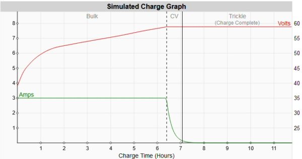
If we are charging these batteries with a 58.8V 3A charger, roughly we are charging each cell at 0.42A (3A / 7) which is well below the standard 2.45A, for the Samsung 50e, used in capacity testing. When charging at 0.42A we would see an increase in capacity of charge, although not tested.
The diagram below shows the charge time for our battery charging at 3A. Time to full charge approx. 7 hours, allow an extra hour on full charge for the cells to balance, the app will show you when all cells are balanced.
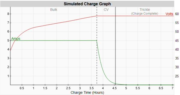
If we are charging these batteries with a 58.8V 5A charger, roughly we are charging each cell at 0.71A (5A / 7) which is well below the standard 2.45A, for the Samsung 50e, used in capacity testing. When charging at 0.71A we would see a decrease in capacity of charge, although not tested.
The diagram below shows the charge time for our battery charging at 5A. Time to full charge approx. 4.5 hours, allow an extra hour on full charge for the cells to balance, the app will show you when all cells are balanced.
Below is a screen shot of the pc communication software set up for our rack battery, 48.1v 13s5p using Samsung 50e cells, voltage ranges from 3920mv to 3100mv (No 3 in the table above). The charge over protection current has been set to 5.5A giving us the option to use a 5A or 3A charger.
BMS Android Apps
The file is a zip file with 3 versions of the app, some versions work better on different phones. Download the files on a pc or laptop, you will need to unzip the files, then transfere them to your phone to install. Some versions of the app work better on different phones and android versions. There is a cutdown version on google play store but does not have all the extended features.
Click here to download the apps
Below is a screen shot of the pc co
PC Software
Below are links for software for the PC data port, its USB drivers and setting up instructions
JBDTools (BMS) Detailed parameter settings
Download and unzip the above files
Click here to download the zipped BMS file
Unzip the BMS file
Install JBDTools (and USB drivers if needed)
Open JBDTools
Click on the "COM" Button and select your com port that the USB is connected to
Click on the "Start" button, if you have selcted the correct com port and the usb drivers are working you should be able to use the software
Press the Open "Eprom" button
Select the unzipped BMS file and open the file
This then will populate the fiekds in JBDTools.
If you make changes to the settings use the "Save Eprom" button to make a back up
Next click the "Write Eprom" button, this should now program your BMS
Check that your settings have been applied by selecting the "Read Eprom button", if your values change back to default setting, re wite the BMS file to the BMS
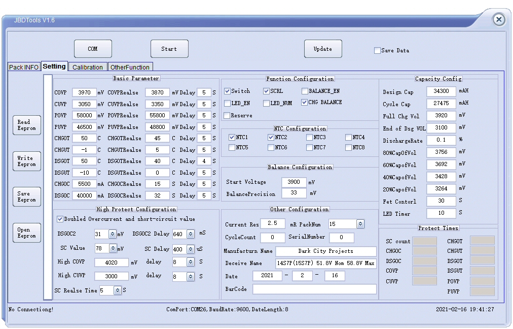
Below is a screen shot of the pc communication software set up for our 14s(15s) battery, 58.8v 14s7p(15s7p) using Samsung 50e cells, voltage ranges from 3920mv to 3100mv (No 3 in the table above). The charge over protection current has been set to 5.5A giving us the option to use a 5A or 3A charger.
Abbreviations
| COVP | Charge Over Voltage Protection |
| CUVP | Charge Under Voltage Protection |
| POVP | Pack Over Voltage Protection |
| PUVP | Pack Under Voltage Protection |
| CHGOT | Charge Over Temperature |
| CHGUT | Charge Under Temperature |
| DSGOT | Discharge Over Temperature |
| DSGUT | Discharge Under Temperature |
| CHGOC | Charge Over Current |
| DSGOC | Discharge Over Current |
| Design Cap | Pack capacity = Each cell (4900mah) x No if cells in parallel (5) |
| Cycle Cap | Pack Actual Capacity = Each cell (4525mAh ) x Number of cells in parallel (5) |
| Full Chg Vol | Designed full charge voltage of each cell |
| End of Dsg Vol | Designed end of discharge voltage of each cell |
| NTC 1 & NTC 2 | Temperature sensors 1 and 2 (on/off) |
| BALANCE_EN | Enable balance during normal running |
| CHG_BALANCE | Enable balance during charging |
