
Bob's Bike Build - Specifications and Parts
2015 GT Karakoram 29" aluminium frame, with Rockshox XC32 front suspension, upgraded
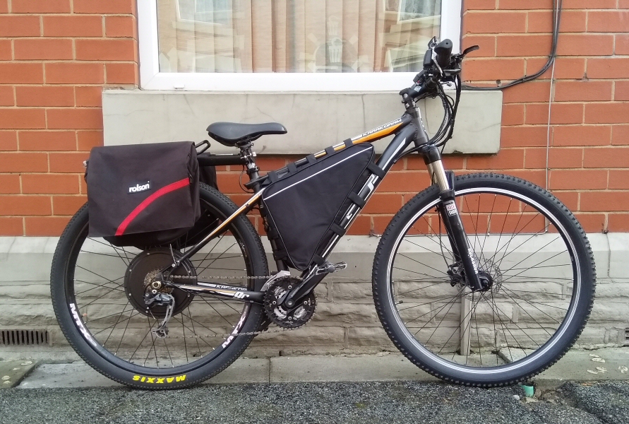
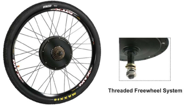
48V 1500W Electric Bicycle Conversion Kit with 29" Wheel (135mm Hub Motor)
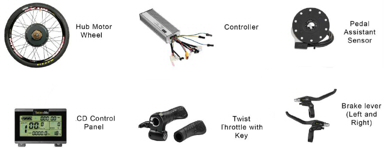
| 29in 48v Hub Motor Rear Wheel Threaded freewheel system 1500w Brushless Gearless Motor Motor Wheel Diameter: 135mm Max Speed: 600 RPM Max Torque: 35 N.M |
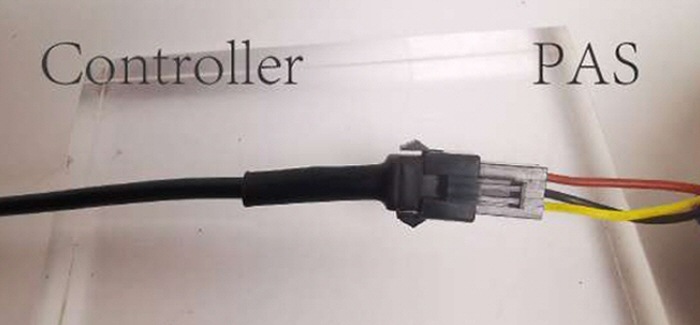
1500W 18 Mosfet 45A Speed controller Display: KT LCD3 Twist throttle with key Brake levers - Left and right Pedal assist sensor (PAS) |
 |
 |
|
| 48V E-Bike LED Light kit | 5mm Torque Arm |
 |
 |
|
| Shimano M355 Hydraulic Brakes | 160mm Brake Discs |
 |
 |
|
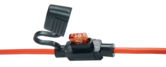
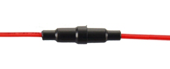
| 50A fuse holder (40a Fuse) | 5A Fuse holder (charging) |
 |
 |
|
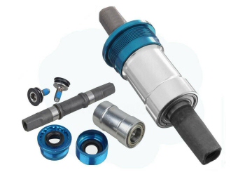
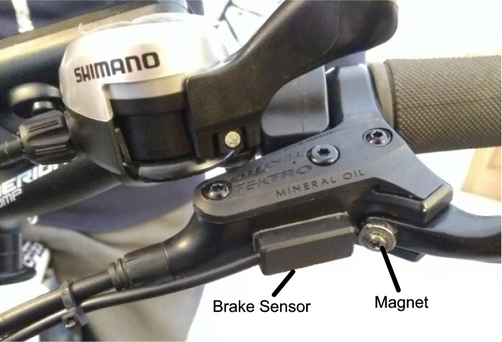
| Magnetic Brake Motor Switches | Bottom bracket |
Choosing an Ebike Kit
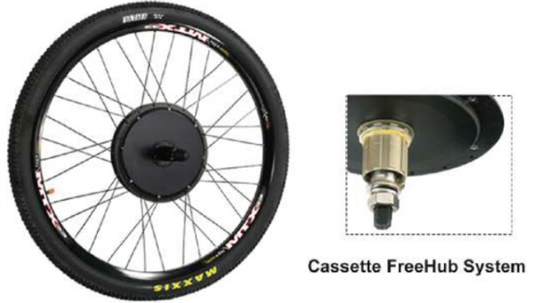
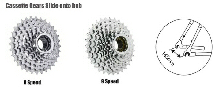
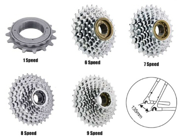
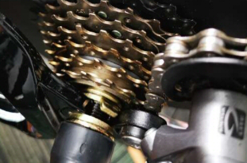
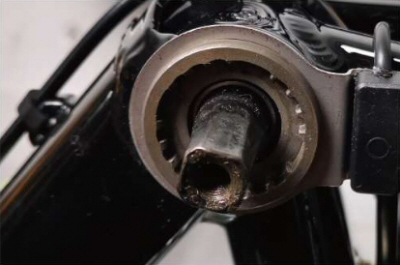
| When choosing the kit you need to know which gear system you bike has. There are two types a threaded freewheel system and cassette free hub system. (pictures below).
The dropout (distance between the rear forks) varies on each bike. The cassette free hub systems are generally bigger, usually having 8 or 9 gears and a dropout of 145mm. The freewheel system has a greater variety of rear gears ranging from 1 speed to 9 speed and a dropout of 135mm. In this build we chose the freewheel hub system with a 7 speed rear gear.
|
The Hubs
|
|
 |
|
|
|
 |
|
|
Threaded freewheel system |
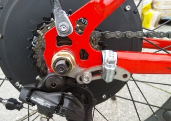
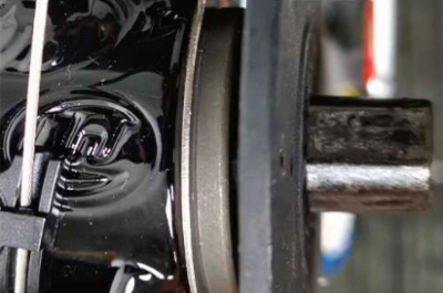
Cassette freehub system |
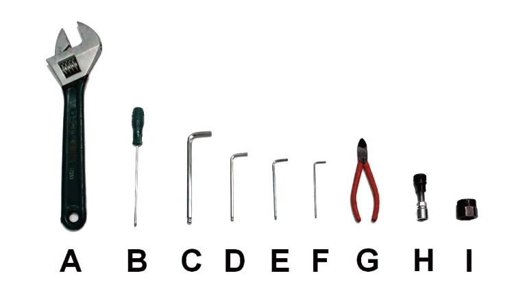
Tools Needed
| A - Adjustabe Spanner B - Philips Screwdriver C to F - Allen keys 3,4,5,8mm G - Side Cutters H - Crank Puller I - Socket Wrench |
 |
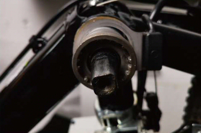
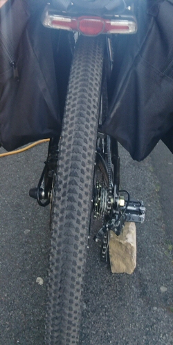
Installing the rear motor wheel
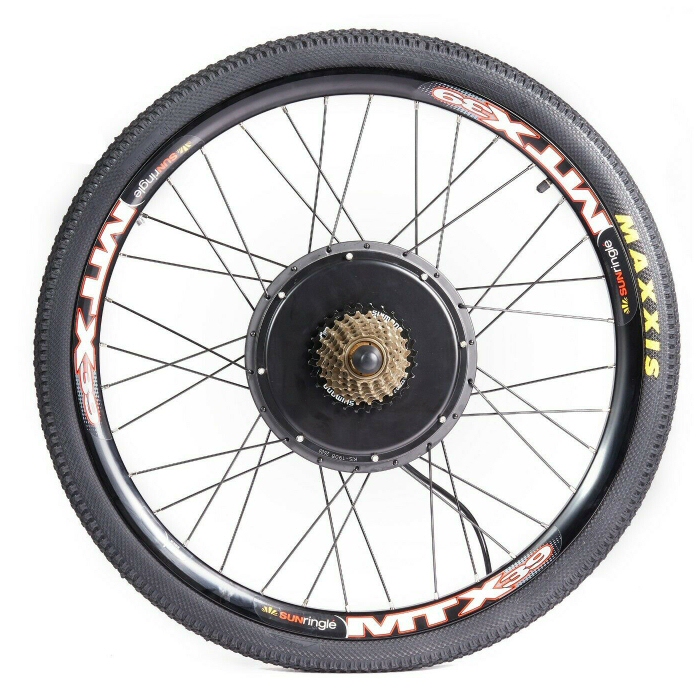
29in Wheel 29" * 2.1" Tyre
1500w 48v Electric Brushless Gearless Motor Rear Hub
Firstly remove the original rear wheel.
Install your own disc brake rotor on motor wheel (if your ebike uses disc brakes)
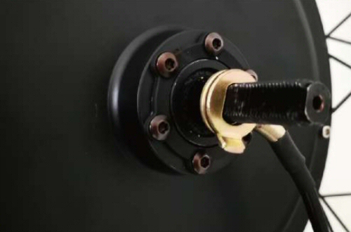
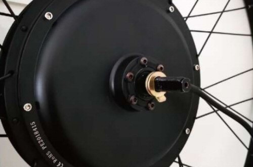
Put the motorized wheel in the rear forks. Note - the motor cable will come out from the left side, the motor axle must be put inside the socket of rear fork. Make sure the spring is at the axel end to protect the cable.
 |
 |
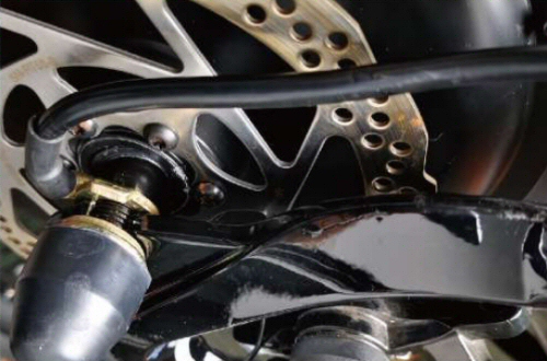
Check the disc brake rotor position, if the distance between rotor and rear fork is less than 15mm then add a washer between the motor axel and fork to adjust the distance. Then fasten all nuts.
 |
 |
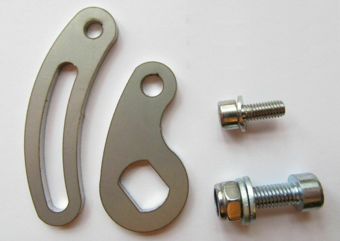
Install the torque arm
|
 |
|
| Torque Arm Heavy Duty 5mm Stainless Steel (14x10mm) |
Picture of torque arm fitted |
|
|
|
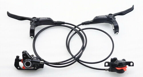
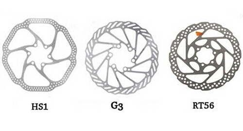
| Shimano Hydraulic Brakes | Brake Discs (3 Types) |
Hydraulic Brakes
We originally had cable disc brakes which could stop a bike with a 500w motor safely. We decided that since we have a 1500w motor we needed a hydraulic disc brake set. Please consider this set a necessity on any motor over 500w !
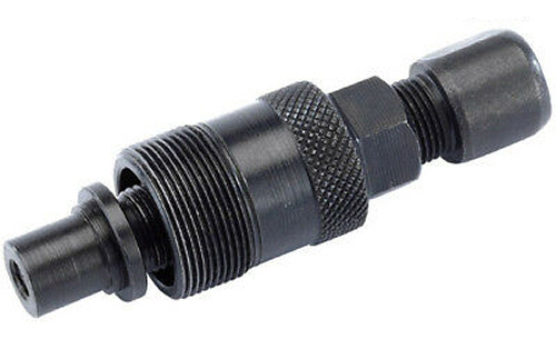
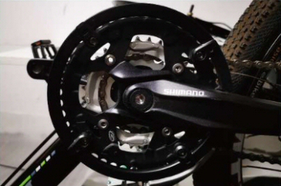
Install the pedal assist sensor
 |
 |
|
|
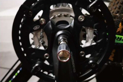
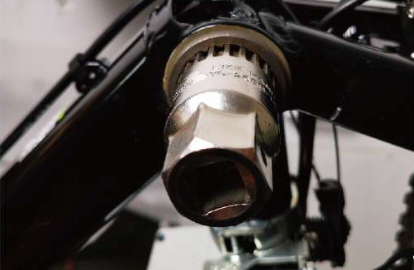
Quality Bicycle Crank Puller |
|
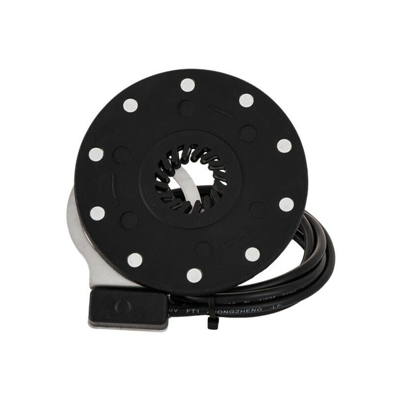
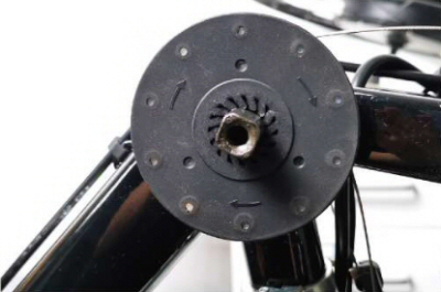
3 Pin Pedal Assist Cadence Sensor (PAS) 10 Magnets |
Instalation guide
PAS (Pedal Assistance Sensor) is a necesessary component of an electric bike in european countries. PAS controls the power supplied to the motor through the angular velocity of the pedal. ie the faster the pedal turns the faster the motor runs
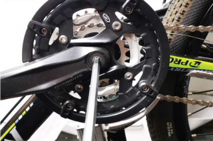
Remove left and right side cranks. Remove your bike's righthand side chainwheel.
 |
 |
 |
 |
Put the PAS signal receiver ring onto the axel and fasten it with a ring washer. Then put the outer magnetic ring next to the ring washer .Check the magnetic ring rotation direction (you will see the rotation arrow on it).
 |
 |
Make sure they do not contact each other by using washers, keeping them with less than 5mm apart. Now you can reinstall the chainwheel and cranks.
 |
 |
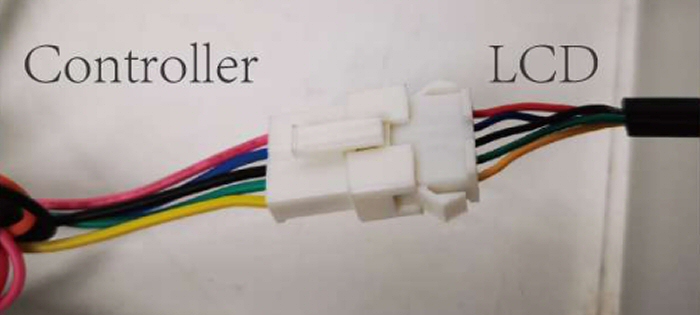
LCD Instalation
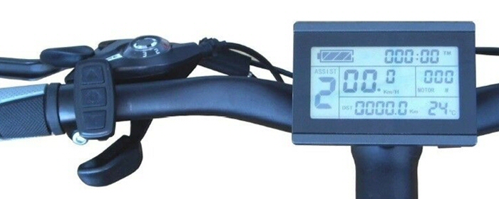
Wind several layers of stickey tape (or large heatshrink) on handlebar so that the LCD mount clips just fit. Install button module on left side (or right side). Clip the LCD screen on handlebar and fasten the two nuts.
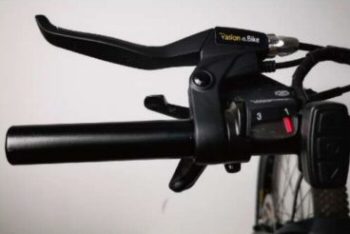
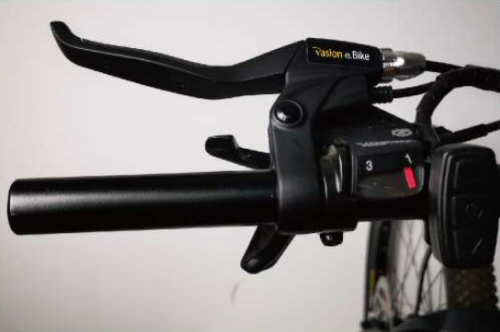
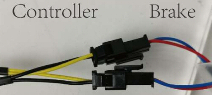
Break levers
Below is how we installed the brake levers, the pictures are from cable brakes. We upgraded to hydraulic brakes.
Fit left and right brake levers
 |
 |
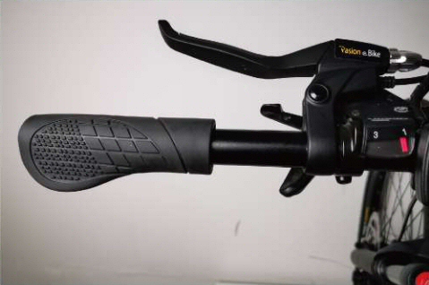
Install left hand side grip
 |
 |
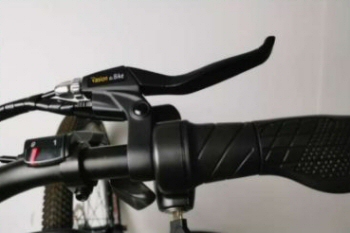
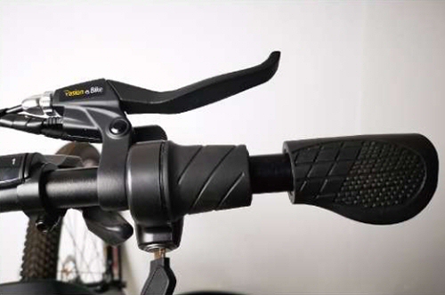
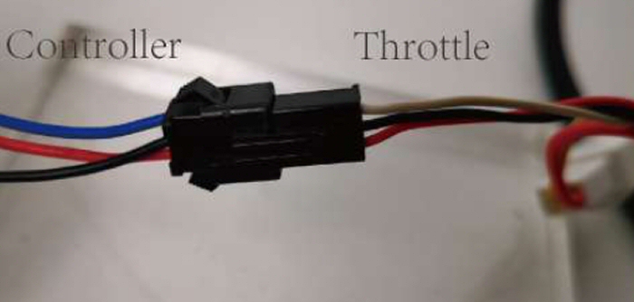
Twist Throttle Mount
 |
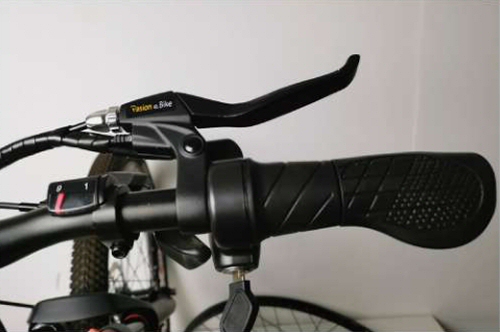 |
Install right hand side throttle and fasten with 3mm socket head wrench.
Install right side grip.
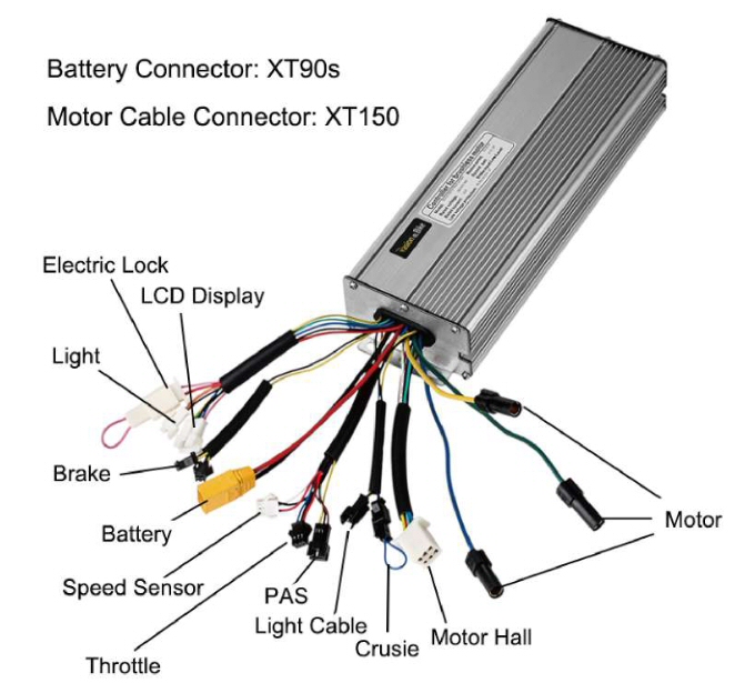
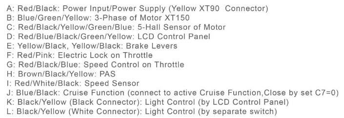
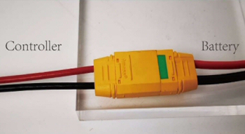
1500W 18 Mosfet 45A Speed controller
 |
 |
 |
 |
 |
 |
 |
 |
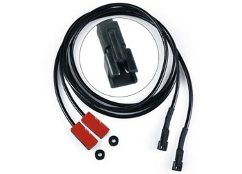
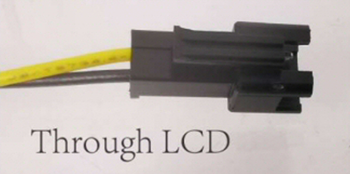
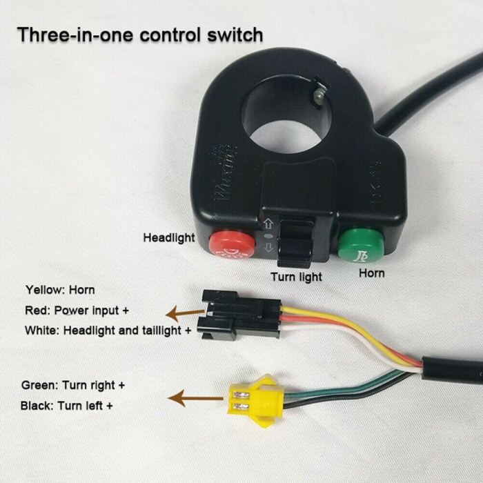
Ebike light control - Black/yellow (Black Connector) 36v or 48v Light Control (by LCD Control Panel)
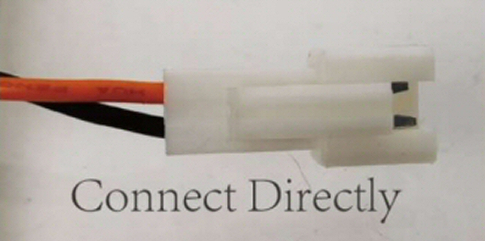
Black/red (White Connector) 36v or 48v Light Control (by seperate switch)
In our case we are sending the control signal for the lights from the LCD display to a wiring loom that comes with the light kit. (Black socket with yellow and black wires.)
 |
 |
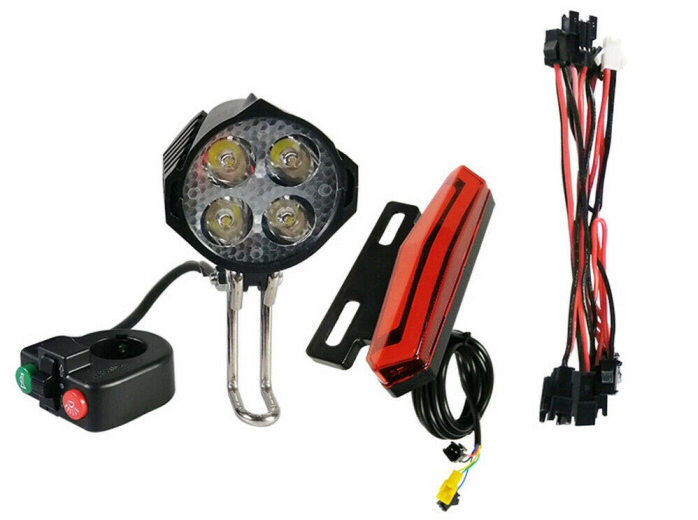
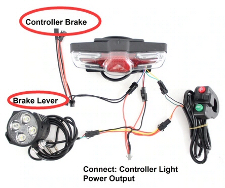
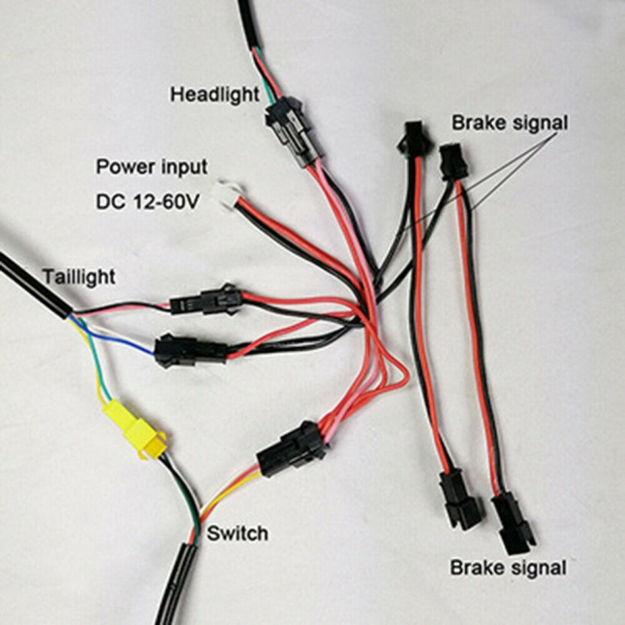
12-60V Ebike lighting set
The ligting set can be controlled by the speed controller via the controlls on the lcd3 display or can be wired direct to the battery. In each case check if the power is less thab 60v as this is the maximum rating of the light set. Controlled lighting uses the "LCD passthrough" (Black connector) connector, and direct lighting is powered by the "Connect directly" (White connector).
|
|
 |
 |
The above pictures show how the light set connects to the bike. The light set has a wiring loom which connects the switch, the headlight (horn is inside the headlight), and the light controll switch. The brake lever wires connect to the loom and back out again to the controller.
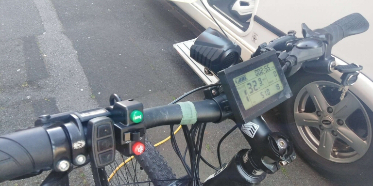
All controlls fitted
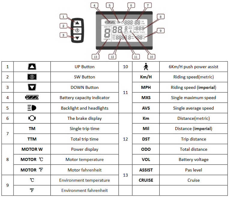
KLCD 3 Control and display unit
Alloy Rear Bicycle Pannier Rack
rack pic
We replaced the adjustable upright supports with 9.5mm aluminium bar for more strength.
 |
 |
|
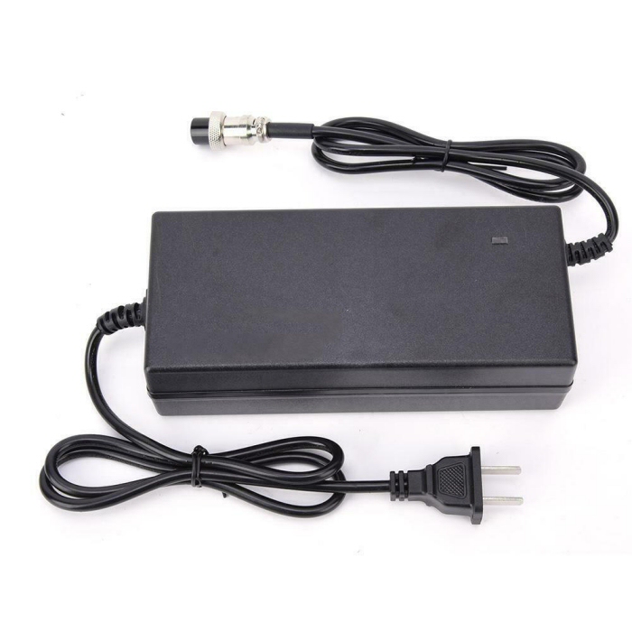
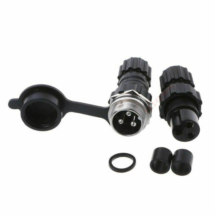
| 54.6V 3A Charger | 3 Pin Charging Port |
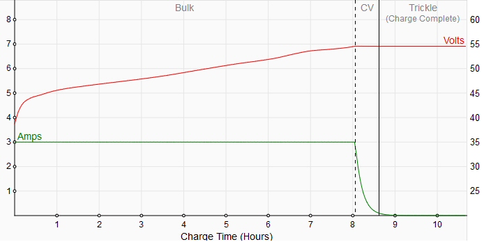
Charge time to 54.6v at 3A charge approx 8.6 hours
LCD3 Display Setup
Normal usage
Turn the power on using the key (and power on with the app if needed)
Pressing and holding the center button for 3 seconds, on the controls, turns bike the display on and displays instantaneous speed, distance, and wattage and more.
Pressing the center button again this takes us to a screen showing average and max values.
Pressing the button again takes us to another screen (which?).
Pressing the button again takes us to another screen (which?).
To turn the display off long press the center button and it will return to the initial screen. If you do not do this it will automatically return to the initial screen.
Holding the up button on the controls when the display is on, turns the display backlight on.
Walk assist - Hold the down button and your bike will move forwards at 0.6 kmph
Power assist level - This setting sets the amount of assistance you will receive from the motor. You can set this from 1 to 5, with 5 being the most power assist.
Cruise function - Hold the up botton for several seconds, the assist level display will change to a C. This will maintain your current speed without using the throttle. To come out of cruise function, use your brakes or throttle and the display will return to your previous power assist level.
Reset trip meter - after about 10 seconds of turning the display on, press and hold the up and down buttons at the same time, the trip meter display will flash, press the middle button to rest the trip meter.
Setup
Before 5 seconds have elapsed, press the up and down buttons at the same time, to enter settings mode.
Press middle button twice to move to the kmph to mph setting. Use the up an down buttons to change to kmph or mph. This also changes the temperature display from F to C.
Press the middle button untill the max assist speed section flashes, then use the up and down buttons to adjust. This speed is the maxium speed that the motor will assist to.
Press middle button untill the display is on the tyre size section. Using the up and down buttons adjust this number to your tyre size, in our case we set this to 26 inch tyres.
| KLCD 3 Instructions | KLCD 3 Extended instructions |
Click here for full LCD3 instructions
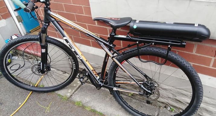
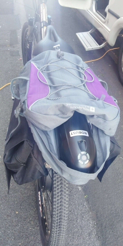
20Ah Lipstick battery installed
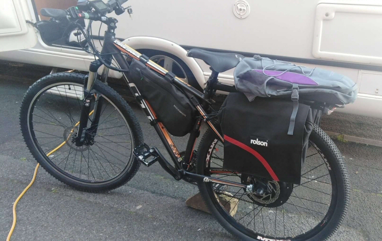
20Ah Lipstick battery, controller bag, rear rack and paniers
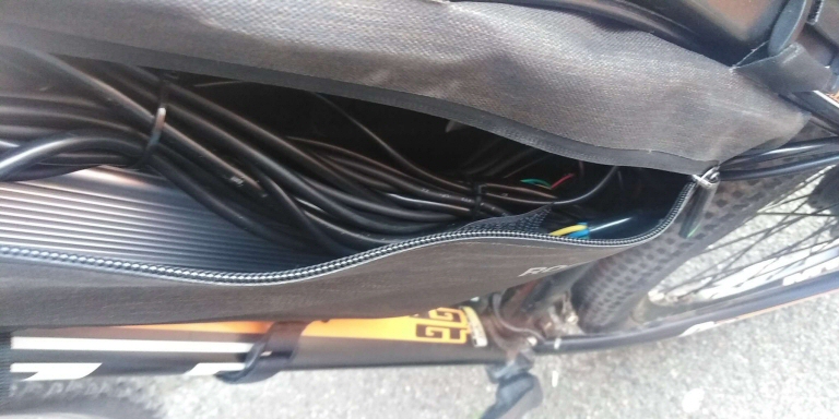
Inside the controller bag - Lots of wires !
 |
 |
|
| Rear lights | Lipstick battery in a bag |
Coming Soon - Bobs bigger battery
